This is part of the Inverter Power project.
Lots of ways to do it, but again I didn’t want to drill a bunch of (large) holes for connectors etc. So, again, routed out the plastic outer storage tubs in the floor, into the bed through a hole with a nice rubber grommet in there. Cut the male end off a 30A RV extension cord so I have a nice sealed female plug, and the same with a male end for a 12/3 extension cord, good for 15A. For storage, and to protect against the elements I put them in little plastic water tight cases, except for the holes I made in the bottom, and I hung the cases on the truck bed wall with aluminum brackets. (Love the flat beak vice grips/hand break)

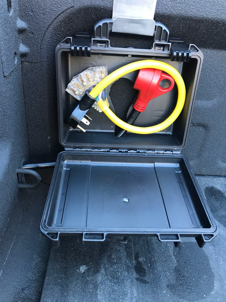
Note 30A RV to three 20A Edison dog bone. Bring on the tools! And the other side the shore power cord:

Connecting the Truck Camper is now a matter of running the cable along side from the shore power connection to the cable from the I/C
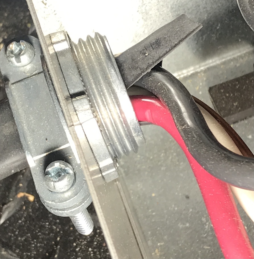
The fiver was a little more involved. First off the shore power connection is 45′ feet away in the back. So there and back would be 90′ of cable. Silly. Somehow I had to tie in to this. I decided to add another transfer switch as per the diagram, to select between Generator and Inverter. Priority is Generator over Shore over Inverter. This is standard procedure and similar diagrams as shown below are in the transfer switch manual. The original one is the grey metal box which I found with the lid off……(Ignore the yellow Romex.) In addition to that, the red hot lead coming out the bottom was chafing on the clamp and would have shorted out eventually and made life very “interesting”. In the pictures I have it pushed in and you can see the damage on the closeup.


Schematic:

Picture of the second transfer switch installed, ready to put the lids back on. If you are doing this….. The transfer switches have delays on the generator connections (20-30 sec) so the generator can stabilize. On the second transfer relay the feed from the first one lined up with generator, and I put the inverter on shore power. I don’t need the delay on the second one and there is a small dip switch on the board with “Delay” and “ON”……. so you put it the other way and you get….. delay. Because you’re reading it upside down….. it says “NO” when in the “NO DELAY” position….. The black cable in the front is from the 30A shore power connector I added in the front of the trailer. (See below)
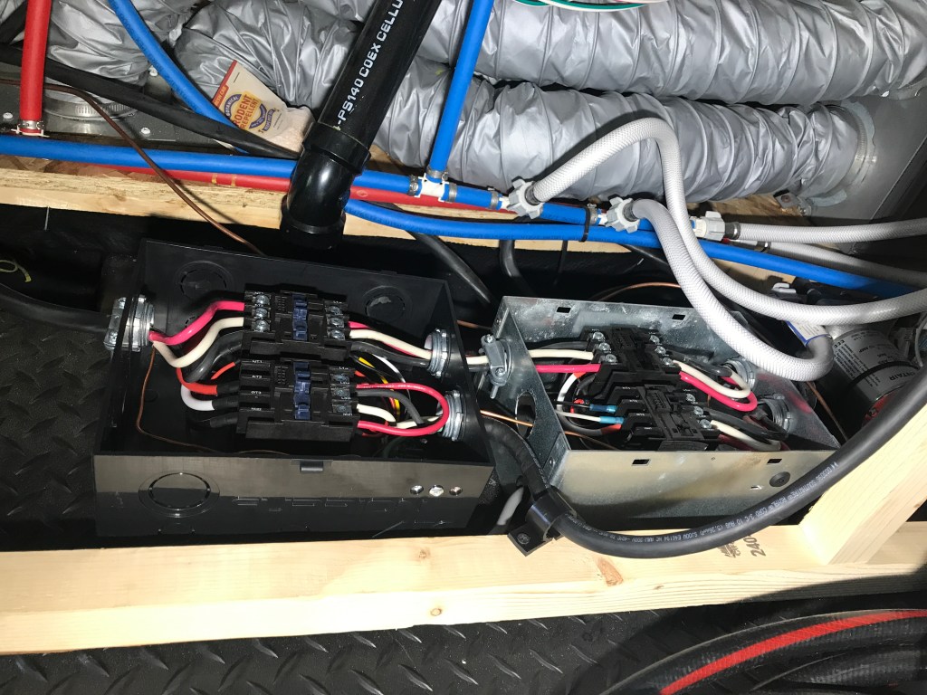
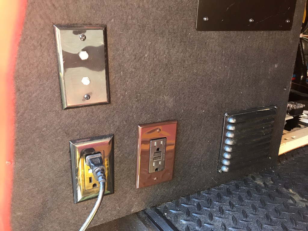
To provide power to the I/C for charging the LFP bank from the generator I added an outlet with a dedicated circuit in the pass through storage. (Hence the yellow Romex) While I was in the breaker panel I added two ammeters to help manage load.
There was one more thing….. If the inverter is supplying power, the breaker panel is powered which sends power to this outlet where the I/C gets it’s “shore power”, if plugged in, which will drive the I/C nuts as it is now powering itself. This is bad. Options are to put a switch in and manually turn the outlet off when switching to inverter, or going outside and pulling the plug. Both of these require remembering to do this….
A better option was to put in a relay in the line between breaker and outlet, and said relay is closed only when there is AC power present from shore power or generator, not inverter. In other words the output of the first transfer relay.
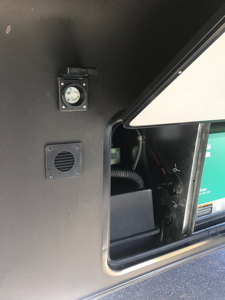
To get in to the camper and to the transfer relays I installed a 30A connector in the front. Some plywood in the back to support the plastic fantastic front.

The dedicated outlet and the relay that powers it. Second Transfer Relay not installed yet. I moved the original one over a bit to make room. The big metal box behind it is the OEM Converter. (Takes 120VAC and provides 12VDC for lighting etc plus charging of the two original house batteries.

Back to Main Page.
